
Thursday, December 24, 2015
Rail Cutting Jigs
So having given you a few days to think about the mystery 3D printed objects I'll put you all out of your misery. They are jigs to help cut rail at the correct angle for making Hudson Type 1 and Type 2 points in O14. While I have the KBscale jigs for actually soldering the rails together they rely on you cutting or filing the rail ends to either 15 or 9 degrees and I found doing this accurately was a bit of a nightmare and so a jig or two sounded like a good option.

The printed jigs are actually the third iteration of the basic idea which was to trap the rail in such a way that a razor saw could cut it at the given angle. The first attempt, which I've unfortunately thrown away so can't show you, used four pieces of 4mm square section styrene stuck to flat sheet, two on each side of the rail. The pieces on each side were offset so that you ran the saw across the rail resting it against the ends of the blocks. It worked well enough to produce the first crossing I made but it wasn't easy to hold the rail still while pushing the saw against the blocks.
The second jig used 12BA nuts and bolts to both clamp the rail and to help position the saw. The screw holes being carefully positioned so that they both allowed the nuts to grip the web of the rail, but also to act as the guide for the saw. While this was much better at keeping the rail in place it was still difficult to keep the saw in place against the upright screws, there was a danger of sawing into the nuts, and the cheesehead screws meant that the jig wasn't very stable on the worktop. It did, however, allow me to build two Type 2 point without requiring any extra filing of the rail ends.

The printed versions continue the idea but without relying on the screws to guide the saw. The two printed parts are used to clamp the rail in combination with grooves in both halves. The slightly bendy nature of the strong and flexible plastic is actually really useful here as it allows you to really tighten the jig so that the rail doesn't move at all. The saw then fits within in the guide formed between the top part and the block on the bottom half making it much easier to cut the rail.

I haven't had a chance to build a point using the new jigs but I have cut a couple of rails to check that they work and they appear to work very nicely which should make it easy to churn out more crossings in the future.
Tuesday, December 22, 2015
Christmas Mystery Objects Quiz
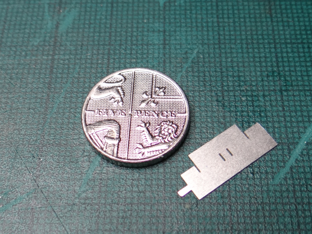
I seem to spend a lot of time over the Christmas period doing quizzes of one form or another. This year the GCHQ one is worth a go if you happen to like your quiz questions on the fiendish side. Anyway I had a Shapeways delivery this morning that contained a couple of test pieces that I thought I'd turn into a mini mystery object quiz. So without further waffle what are these?


Sunday, December 20, 2015
Driven By Him
So here we are, the last post on the build of this the third Clayton prototype (the second never got made up but allowed me to test the keeper plate). The driver is now in place which means the whole loco now weighs in at 34g. Possibly a little light for an O14 loco but there isn't much space to add extra weight.


Obviously it's not entirely finished as it needs painting and the name and works plates fitting but these will be left to David as my painting skills aren't up to producing a loco that would fit in well with the quality of Rhyd. It seems strange packing it up to send it off to it's new home as I've never built a model for anyone else before. Hopefully David will enjoy it and if you see Rhyd at an exhibition you might even see the Clayton working the quarry tramway. For everyone else here is one final video of the loco in action.


Obviously it's not entirely finished as it needs painting and the name and works plates fitting but these will be left to David as my painting skills aren't up to producing a loco that would fit in well with the quality of Rhyd. It seems strange packing it up to send it off to it's new home as I've never built a model for anyone else before. Hopefully David will enjoy it and if you see Rhyd at an exhibition you might even see the Clayton working the quarry tramway. For everyone else here is one final video of the loco in action.
Starlight Express
One of the first comments I received when I announced I was working on a model of the Clayton was that the light mouldings really were crying out to be fitted with working lights, and who am I to refuse such a sensible suggestion. The problem is that while the mouldings are big in relation to the size of the model they still aren't very large. Fortunately LEDs are available that will fit but they are very very small.
The smallest surface mount components I've used before are the resistors in the Hudson-Hunslet, which come in a 1206 package. They are known as 1206 as that is the imperial measurements of the component, i.e. 0.126" by 0.063" or in metric just 3.2mm by 1.6mm. For the lights on this loco I've had to go for LEDs in a 0402 package which is 0.039" by 0.020" or an eye wateringly small 1.0mm by 0.5mm. Given that those dimensions are for the entire LED you can probably imagine just how small the two contacts are that you need to solder wires to. My eyesight for close work might be quite good and I have a brilliant magnifying lamp on my desk but I don't think I would have the patience or dexterity to wire these up. Fortunately you can buy them pre-wired on eBay! This helps but the wire itself (referred to as magnet wire) is also ridiculously thin so it's still a fun challenge wiring these up.
Of course there isn't just the LEDs to wire in, but a resistor to protect them from the full track voltage (2.2K Ohm in this case) and a capacitor to help reduce flickering all of which need to be connected together and then stuffed into the small space behind the motor.

As you can see there is quite a bit of stuff, even if some of those wires were trimmed back before I finished) to get into the body so there was a fair amount of careful stuffing involved. Once the body was on the result though is this.
I could probably have used a slightly bigger resistor to drop the brightness a little further but for a loco that originally worked in a long dark tunnel this seems okay, and a bigger value capacitor might have reduced the flickering a little further, but in general I'm really happy with the result.
Saturday, December 19, 2015
Powered Chassis Test
After a break of afew days due to visiting family I'm now back to building the Clayton loco and fortunately, given the little time remaining to post it on Monday, things seem to be going quite well, although the carpet monster did eat the small pulley although it then spat back two 1.5mm bearings! Anyway here is the current state of play.
The main job today is to fit and wire up the lights, and then I can add the final body details. Then tomorrow I need to finish the driver figure and to give the whole thing another good test run.
 After a break of afew days due to visiting family I'm now back to building the Clayton loco and fortunately, given the little time remaining to post it on Monday, things seem to be going quite well, although the carpet monster did eat the small pulley although it then spat back two 1.5mm bearings! Anyway here is the current state of play.
The main job today is to fit and wire up the lights, and then I can add the final body details. Then tomorrow I need to finish the driver figure and to give the whole thing another good test run.
Tuesday, December 15, 2015
A Tiny Worker (Bee or Ant)
As you probably all gathered I really enjoyed building the Blacketty Water bridge model for this years Dave Brewer Memorial Challenge. Being given a set of constraints and a time limit helped me to focus and build something I'm really proud of as well as learning a whole new bunch of skills. I was expecting the challenge for 2016 to be announced sometime early next year, given that this years challenge was announced at the end of February, so I was a bit surprised when the announcement came at the end of November. There will be a blog post about the new challenge at some point as I do have an idea for it, but this post is about another challenge that I'm going to enter that was announced on the same day.
In general I'm not a forum person, the one exception to this is Narrow Gauge Railway Modelling Online (usually just abbreviated as NGRM) where I'm now a frequent visitor and poster. In the past they have held modelling challenges and they have decided it is time for another one, specifically to scratch build a locomotive. There is a full description and set of rules on the forum (you have to be a member to read them I'm afraid), but the motivation is
I've never scratch built a loco before, and certainly never a chassis, but personally it wouldn't be a challenge if I didn't go all in at level 3! Having decided to enter though I had no idea quite what I was going to try and build but, not surprising given the locos I've been designing and building recently, I thought I'd look for something small and quirky.
Fortunately the UK has it's fair share of both small and quirky locos so I didn't have to look very hard to find something and here it is (photo from Wikipedia).

This is one of two locos (this one is Bee the other is Ant) that were built in 2004 for the Great Laxey Mine Railway on the Isle of Man. They are replicas of the original locos used at the mine which were unfortunately scrapped in the 1930s.
It should be clear from even just a quick glance at the photo, that this loco is both small and quirky. Having managed to find a set of drawings (thanks Rob) that appeared in the April 1991 issue of 009 News, I know just how small it is. According to the drawings it's just 4' 9" from rail to chimney top, but more interestingly the track gauge is just 19", which is really very narrow.
As yet I haven't decided what scale to build a model of this loco in. I had wondered about using a standard track gauge (9mm, 14mm, 16.5mm etc.) and then picking a scale to match, but if I want to be able to put the loco with any scenic stuff or figures etc. then using a standard scale and hand building track to match probably makes more sense. My current thinking is possibly to go up yet another scale from my usual modelling to 16mm to the foot scale, which will still give a tiny loco; just 76mm from rail to chimney top. I need to make a few more measurements before making a final decision though.
In general I'm not a forum person, the one exception to this is Narrow Gauge Railway Modelling Online (usually just abbreviated as NGRM) where I'm now a frequent visitor and poster. In the past they have held modelling challenges and they have decided it is time for another one, specifically to scratch build a locomotive. There is a full description and set of rules on the forum (you have to be a member to read them I'm afraid), but the motivation is
This challenge has been created to promote scratch building using various tools and materials. Over the years I have seen some very interesting locomotives scratch built using the very basic of hand tools in plastic, brass, and complete mix of other materials. You don't have to be a professional model maker to take part, all you need is patience and basic hand tools. Entrants are asked to respect the spirit of the competition when taking part.To try and interest as many people as possible there are three different levels:
- Level 1: scratch built body on a ready to run chassis.
- Level 2: scratch built body on a modified ready to run chassis (e.g. Farish 08 with added cylinders, valve gear etc.)
- Level 3: scratch built body and chassis.
I've never scratch built a loco before, and certainly never a chassis, but personally it wouldn't be a challenge if I didn't go all in at level 3! Having decided to enter though I had no idea quite what I was going to try and build but, not surprising given the locos I've been designing and building recently, I thought I'd look for something small and quirky.
Fortunately the UK has it's fair share of both small and quirky locos so I didn't have to look very hard to find something and here it is (photo from Wikipedia).

This is one of two locos (this one is Bee the other is Ant) that were built in 2004 for the Great Laxey Mine Railway on the Isle of Man. They are replicas of the original locos used at the mine which were unfortunately scrapped in the 1930s.
It should be clear from even just a quick glance at the photo, that this loco is both small and quirky. Having managed to find a set of drawings (thanks Rob) that appeared in the April 1991 issue of 009 News, I know just how small it is. According to the drawings it's just 4' 9" from rail to chimney top, but more interestingly the track gauge is just 19", which is really very narrow.
As yet I haven't decided what scale to build a model of this loco in. I had wondered about using a standard track gauge (9mm, 14mm, 16.5mm etc.) and then picking a scale to match, but if I want to be able to put the loco with any scenic stuff or figures etc. then using a standard scale and hand building track to match probably makes more sense. My current thinking is possibly to go up yet another scale from my usual modelling to 16mm to the foot scale, which will still give a tiny loco; just 76mm from rail to chimney top. I need to make a few more measurements before making a final decision though.
The Keeper Plate
One of the parts I had to redesign from the second prototype of the Clayton was the stainless keeper plate. If you remember I'd managed to design it 0.2mm too wide and reducing the width by hand was a nightmare due to the strength of the stainless steel. So I altered the design to remove 0.1mm on both sides, and opened out the screw holes slightly for an easier fit. The larger holes meant a change to the rebate for the head of the screw as well.


As you can see the changes worked well and everything fits together nicely. The two bolts are lightly glued into place just to make sure they don't come loose, and while the layshaft is now fixed in place (the two worms are fixed to the layshaft with Loctite which holds everything firmly in place) everything else is removable just by undoing the two retaining screws. Next job will be to strip it down again, and fit the pickups and associated electrical bits so that I can get it running up and down my test track.


As you can see the changes worked well and everything fits together nicely. The two bolts are lightly glued into place just to make sure they don't come loose, and while the layshaft is now fixed in place (the two worms are fixed to the layshaft with Loctite which holds everything firmly in place) everything else is removable just by undoing the two retaining screws. Next job will be to strip it down again, and fit the pickups and associated electrical bits so that I can get it running up and down my test track.
Monday, December 14, 2015
The Bell
A quick update on another detail for the Clayton loco, this time it's the bell.

I don't think I mentioned this on the first prototype build but I've produced it in the same way by soldering a 4mm pinpoint bearing to an etched stand. Nice, simple, and fairly convincing from normal viewing distances.

I don't think I mentioned this on the first prototype build but I've produced it in the same way by soldering a 4mm pinpoint bearing to an etched stand. Nice, simple, and fairly convincing from normal viewing distances.
Sunday, December 13, 2015
Some Assembly Required
After spending the day with friends I've done a little more on the Clayton build, specifically the rather fiddly brake leaver. This bit hasn't changed since I built one up for the first prototype so it still consists of eight tiny etched parts on a piece of 0.33mm nickel silver wire. Last time I found getting the front and back layers, which slot through the 3D printed body, aligned and straight very difficult, so the tool I included on the etch this time has two slots to make assembly easier.


So building the brake lever basically involves slowly laminating seven of the eight parts using the wire to help align them as well as keep them together. I pas the wire through a hole in piece of wood as well to help keep everything still while dabbing at it with a hot soldering iron. The eighth piece (the front support) is then threaded onto the wire with some solder paste on the wire and the whole thing then slotted into the etched tool to make sure the front and back supports are properly aligned. A quick touch of the soldering iron then fixes the front support in place and with the slots in the tool being the same as on the 3D printed body the completed brake just drops into place.
The tool also has a third use, in that the sticky out bit on the end can be used to make sure all the slots in the body are clear of wax support material so that the pickups, brake, and bell stand will all fit without being forced.
Tuesday, December 8, 2015
Phosphor Bronze Staples
If you've been following along for any reasonable length of time then you'll know that the main area that seems to trip me up building or designing model locomotives is getting the pickups to work properly. On the Clayton loco I think I've hit on a fairly good way of fitting the pickups where what looks like a staple of phosphor bronze strip is pushed through slots in the model from the inside with the ends then bent back at an angle against the outside of the body so that they rub on the rear of the metal wheels. The problem is accurately making the initial staple shape so that it fits perfectly as that helps with setting the tension of the pickups which if not right can affect the running of the model.
On the first prototype I folded up the staples by eye and while they were fairly good they weren't a perfect fit. With the addition of the keeper plate and retaining screws this is even more of an issue as I need to make sure the pickups are flat on the inside so they can't short against the screws. To help with this I designed an etched part to act as a forming tool (it actually has other uses so you'll see this part again).


The tool works well and as you can see the fitted pickup lays nice and flat against the inside of the body so it was well worth adding the tool to the etch. Hopefully it's other use will prove as successful but you'll have to wait a little to find out.
On the first prototype I folded up the staples by eye and while they were fairly good they weren't a perfect fit. With the addition of the keeper plate and retaining screws this is even more of an issue as I need to make sure the pickups are flat on the inside so they can't short against the screws. To help with this I designed an etched part to act as a forming tool (it actually has other uses so you'll see this part again).

The tool works well and as you can see the fitted pickup lays nice and flat against the inside of the body so it was well worth adding the tool to the etch. Hopefully it's other use will prove as successful but you'll have to wait a little to find out.
Monday, December 7, 2015
Weather Protection
With the base kit for the Hudson-Hunslet now out and selling well I've turned my attention back to producing a few cab varieties to help people customize their models. Today I got the test etches back for all three designs and have quickly put them together, not that there is actually much work involved.


So from left to right we have an open cab based on the one fitted to Macnamara at the Leighton Buzzard Railway. Then there is the half-open design which is inspired by the one on LCWW18 which is part of the Moseley Railway Trust collection. Finally we have the fully enclosed cab similar in design to the one fitted to Creepy which can also be found at Leighton Buzzard. If you fancy adding a cab to your model then All three cabs are available to buy from Narrow Planet.


So from left to right we have an open cab based on the one fitted to Macnamara at the Leighton Buzzard Railway. Then there is the half-open design which is inspired by the one on LCWW18 which is part of the Moseley Railway Trust collection. Finally we have the fully enclosed cab similar in design to the one fitted to Creepy which can also be found at Leighton Buzzard. If you fancy adding a cab to your model then All three cabs are available to buy from Narrow Planet.
Never Going Back Again
I've now made a start on building the third Clayton prototype. I'm still waiting on the etched parts to arrive (they've been posted so blame Royal Mail) so while I can't start on the body yet I can get to work on most of the mechanical aspects.
One of the main changes from both my approach to designing the Hudson-Hunslet and the first Clayton prototype was the decision to use a keeper plate and to assemble all the drive components outside the model. This means I can put together the layshaft and the wheelsets in comfort without having to try and fit everything together inside the body.

Compared with trying to fit gears inside a body this is so easy that I'm never going back to the old approach unless forced to do so for some reason.
Saturday, December 5, 2015
Turn to the Right
Having now recieved my order for more rail I've continued on with my O14 point building experiment. The first attempt was for a very tight Type 1 point which in retrospect was going to be a struggle even for short wheelbase locos so for my second attempt I've switched to the slightly less severe Type 2 point. Of course with more rail to hand I've gone a lot further than just building the central frog section, in fact I've built an entire point.


I've deviated from the suggested instructions in quite a few places though as I've built the point onto copperclad sleepers rather than the suggested plastic sleepers. This meant that I had to gap the rails to ensure that the polarity of the frog could switch when the points changed. I also simplified the tiebar slightly by not trying to fit nice looking plates and rivets but using a bit of wire instead. Of course photos on their own don't show you if any of this was successful or not so here is a video of me testing it.
So yes it does work, but I'm not entirely happy with it. Mostly I'm not happy with the hinges. Drilling the holes to make the two parts of the rail line up properly was a real pain. So having recently seen someone else build one without hinges where they relied on the rail flexing instead I'm going to have another go and see if that is a better approach. Still not bad for a first attempt.
Monday, November 30, 2015
A Better Fit
Late last week I had a delivery from Shapeways which contained the next iteration of the parts for the O14 Clayton battery electric loco I'm working on. This is now version three of the design and it looks like I've solved all the outstanding problems with the previous version.

The main differences are to the way the parts fit together. Firstly I've narrows the steel weight slightly (which involved changing the shape of the cutouts for the screws) so that it will fit inside the body without distorting the sides. In the previous design the two main parts of the model were mostly held together as a friction fit, but only along two small surfaces (the back and front of the top piece fit against the front buffer beam and the front of the driver area). In theory this was enough, but often the parts would warp ever so slightly during the printing process and although they would hold initially would spring apart just by sitting there. Also if viewed from low down there was a slight visible gap between the two parts above the wheels.
I've solved the problem by adding more material to both parts to increase the surface area of the interlocking sections. This means there is now a block on the bottom of the upper part that slots between two of the supports in the bottom half to keep the flat rear area flat. To make sure the front part stays together, and to get rid of the slight gap, I've extended the body sides upwards so that they fit inside the top half by a couple of mm. This seems to work so well that once the parts are together they require a fair amount of force to separate. Combined with the retaining screws it looks as if it will be a nice solid model once I've built it up.
Talking of building it, this model is going to be a little different to every other one I've built as once it's running it will be packed up and shipped off to it's new owner. When I was visiting ExpoNG I spent a very enjoyable evening drinking beer and talking railways with David John the builder of the wonderful O14 layout Rhyd. He was really taken with the first prototype of the Clayton and has asked me to build one to run on the quarry tramway. Normally I'd have waited and built up another print rather than what is in essence a prototype model, but as it is destined to be one of David's Christmas present I don't have time to order more parts. It will also be heading to David unpainted as I feel that my loco painting skills (wave an aerosol can at it) fall well below that of the other locos on the layout. Anyway David has kindly agreed that I can document the build and hopefully at some point there will be photos of it earning it's keep on Rhyd.
Thursday, November 26, 2015
The Armless Eunuch
One of the things missing from my prototype Clayton build was a driver. Trying to find an appropriate figure proved more difficult than expected for two reasons. Firstly there isn't much space for a driver in the Clayton and secondly all the controls are on the right hand side of the driver which seems to differ from many other locos and so most driver figures have the left arm posed for controlling things not the right. The third problem was that all the photos I've seen of the loco in use show the driver in high-viz clothing so a an early 20th century tractor driver, for example, wasn't really going to fit the bill.
Fortunately while browsing around I came across the figures made by Andrew C Stadden which included a driver figure with his right arm out and in high-viz clothing so I ordered one.


When the figure arrived I was happily surprised to find that it actually comes with a choice of arms so that you can easily pose the drive with either arm bent or outstretched. Unfortunately his wide leg pose meant he wouldn't fit in the rather restricted driver area of the Clayton. Even bending the legs closer together didn't narrow him down far enough, so in the end I had to use a razor saw to castrate the poor bloke! The cut allowed me to force the legs closer together (the pewter the figure is cast in really doesn't bend well, so it takes some considerable force) and close enough for him to sit in position. I'll tidy up the wound with a bit of miliput when I add the arms, but I think he will work quite nicely. Even though he is quite heavy, he doesn't cause any problems in the original prototype model without the steel keeper plate so should be fine in the next build.
Sunday, November 22, 2015
The Makings of a Point
I've really enjoyed working in O14 building the Clayton loco, but if I want somewhere to run the loco that isn't a simple straight bit of track I'm going to need to build some points. When I was at ExpoNG I picked up both the Type 1 and Type 2 crossing jigs from KBscale in preparation for this but it took until this weekend to find time to have a go. Even with a jig to help hold all the parts it's still quite tricky (or maybe I just haven't had enough practice). The first problem is finding a reliable way of cutting/filing the ends of the rails at 15 degrees. In the end I built a small jig from styrene which seems to do the job but it feels like there should be an easier way. Once all the rails have been cut and fitted to the jig the problems don't end. Because the jog is metal it's impossible to get enough heat into the join with my soldering iron as it just soaks into the jig instead. The trick is to use the kitchen blow torch (usually used for creme brulee) to pump in lots of heat.

Once it's cooled and cleaned up it looks as if it will do the job nicely. Unfortunately I then cut the rails back but measured badly so they are too short for the type 1 turnout I was trying to build. Not to worry though as the practice was well worthwhile. Unfortunately I seem to be almost out of the PECO IL-115 rail so will have to order some more before I can have another go. Also looking at the instructions I'm not sure I like the suggestions for hinging the switch rails (a wire down through the sleeper). I'm wondering if I can just do without a hinge and rely on the slight flex of the rail, but that experiment will have to wait until I get some more rail.

Once it's cooled and cleaned up it looks as if it will do the job nicely. Unfortunately I then cut the rails back but measured badly so they are too short for the type 1 turnout I was trying to build. Not to worry though as the practice was well worthwhile. Unfortunately I seem to be almost out of the PECO IL-115 rail so will have to order some more before I can have another go. Also looking at the instructions I'm not sure I like the suggestions for hinging the switch rails (a wire down through the sleeper). I'm wondering if I can just do without a hinge and rely on the slight flex of the rail, but that experiment will have to wait until I get some more rail.
Saturday, November 21, 2015
The Fall of Jerusalem
It's been two years since I last blogged about Jerusalem, and almost two years since I started looking at modelling in OO9. In all that time Jerusalem has hardly been used, and in fact for over half of that time the layout has been stored in the loft to give me more space to model other things. While I enjoyed building Jerusalem and learnt a lot I'm happy to admit that there were many things that were wrong with it. The curves were two tight for a mainline, as seen by the problems with the carriage and the tunnel, the track was badly laid which led to some derailments and the points didn't work well as I relied on the blades to switch the power. In fact the whole layout concept was a serious compromise.
If you remember back to the very beginning of Jerusalem the choice of building in N gauge was purely motivated by me wanting a continuous run layout and not having the room to build such a layout in OO gauge. In retrospect this was a mistake as I'm much happier working in 4mm to the foot scale or above than the 2mm to the foot of N gauge. So when tidying the loft last weekend I made the decision that given all the problems with Jerusalem I was never going to go back to it, and will probably never return to such a small scale either, so the layout was simply taking up valuable storage space.

So as you can see the layout has come down from the loft and anything useful has been stripped from the layout, and the board has now been dumped in the garage ready to go out with the rubbish (or to the tip if I can't be bothered breaking it down further). Some of the parts, like the trees, might be reusable in 4mm scale but I'll hold on to the rest as well as there is no resale value in a few painted animals and some dry stone walling. The loco and rolling stock though are likely to be sold to provide funds for more modelling as it seems silly having them sat collecting dust when I have no sentimental attachment to them.
If you remember back to the very beginning of Jerusalem the choice of building in N gauge was purely motivated by me wanting a continuous run layout and not having the room to build such a layout in OO gauge. In retrospect this was a mistake as I'm much happier working in 4mm to the foot scale or above than the 2mm to the foot of N gauge. So when tidying the loft last weekend I made the decision that given all the problems with Jerusalem I was never going to go back to it, and will probably never return to such a small scale either, so the layout was simply taking up valuable storage space.
So as you can see the layout has come down from the loft and anything useful has been stripped from the layout, and the board has now been dumped in the garage ready to go out with the rubbish (or to the tip if I can't be bothered breaking it down further). Some of the parts, like the trees, might be reusable in 4mm scale but I'll hold on to the rest as well as there is no resale value in a few painted animals and some dry stone walling. The loco and rolling stock though are likely to be sold to provide funds for more modelling as it seems silly having them sat collecting dust when I have no sentimental attachment to them.
Sunday, November 8, 2015
Canopus: Altering the Kit Parts
It's been almost a year since I discovered that a number of the parts in the Backwoods Miniatures kit of Canopus that I was building were the wrong size. Annoyingly this seems to be a fairly well known problem so anyone who builds the kit finds themselves having to alter or replace a few parts. Specifically the slide bars sit too close to the frames and the connecting rods aren't long enough. I solved the problem of the connecting rods by having a new set etched back in February, but the slide bars needed surgery.
Having now released the kit for the Hudson-Hunslet and finished my entry to the Dave Brewer challenge I really had no excuse to use to put off having another go at finishing Canopus so today I set about altering the slide bars and building up the crossheads and piston rods.

It turned out that altering the slide bars wasn't as bad as I expected. Basically I cut them in half soldered in a piece of scrap etch and then filed back some of the central mount to allow the wider version to sit in the frames properly. From a trial fitting this looks to have worked nicely.
Strangely the crossheads and piston rods were much more trouble to assemble than altering the slide bars. Each crosshead is made from two layers soldered together with the piston rod wire trapped between them. While folding the etch in two and soldering things together works well cleaning up the grooves to allow them to run smoothly on the slide bars is a bit more of a pain. After a bit of swearing and filing they do now seem to fit and slide nicely. A quick test fit of one of my replacement connecting rods also shows that these fit within the crosshead nicely. This means the next step is to use a rivet to join the crosshead and connecting rod. Hopefully you won't have to wait almost a year to see how that turns out.
Monday, November 2, 2015
And The Winner Is...
Having worked on my bridge model for about four months the good news is that my careful packing meant that it arrived safely at ExpoNG on Saturday along with eight other entries in a variety of scales.


The winner was "The Cutting" by Derek Harris. As you can see in the photo above the presentation was very clever as it forced you to look down on the model, just as you would if peering over a wall to look down into a cutting. I'm not going to comment on any of the models more than that as after one conversation on Saturday I found that even positive comments could be easily misunderstood given I had a model in the competition.
Given that I held off on showing the completed diorama before Saturday here it is in all its glory along with a label and more importantly my first exhibition badge (these are handed out at most exhibitions to each layout on show).

Usually people stick the exhibition badges to the layout display board but as I don't have one for the bridge, and it's unlikely to be displayed at any other exhibition in the future I'll just carefully store the badge away with the model.
I had a lot of fun building the bridge and I've improved my modelling skills no end, so regardless of the competition result, I'm calling this a win. Now I just have to wait and see what next years challenge will be and if it similarly captures my imagination.
Down at the Bottom of the Garden
So less than an hour after getting home from ExpoNG yesterday (there will be a post on that later) I was stood at the bottom of the garden camera in hand waiting to watch a train go by. Of course I wasn't interested in the local service train but the second running this year of the Tin Bath. Since February we've done enough work in the garden that I could actually get to the bottom fence and one of the fence posts made an excellent tripod.
Tuesday, October 27, 2015
Kits, Kits, and Yet More Kits!
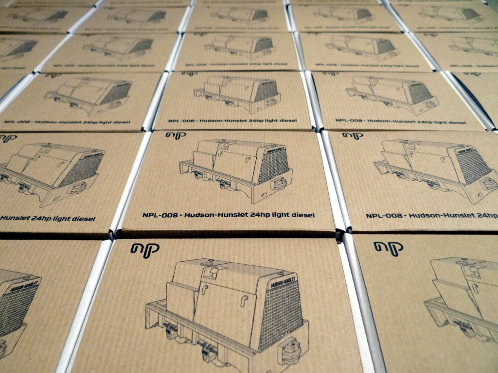
I've now finally finished packing all thirty of the first batch of Narrow Planet kits for my Hudson-Hunslet locomotive. Most of this batch has already been sold although a handful will be on sale on Saturday at ExpoNG. If you've ordered one and are expecting it in the post then I'm just organizing the padded envelopes and should be able to post them out by Monday at the latest.
I'm amazed how popular the kit has been. So popular in fact that we are already planning a second batch!
Monday, October 26, 2015
Signs of Life
Now I know I said I wouldn't post any more photos of the diorama until after the next Saturday, but that doesn't stop me showing you another small detailing piece I put together yesterday.
The railway line that this bridge forms part of was originally built across Duchal Moor to take people out to the shooting butts and was locally known as the Grouse Line. Given it's history it would seem that if I wanted to add any wildlife to the model, it should be a grouse. Unfortunately while I looked high and low for a model I could buy I couldn't find anything. The solution, as with pretty much all of the diorama, was to make one from scratch. To make it obvious what the bird is supposed to be I opted to model a black grouse with it's distinctive red wattles over the eyes.


In theory I had an easy to follow plan. Make an outline from fine wire, fill out the outline, and then paint. The first step was easy. I found a nice drawing online which I then scaled down to the right size to use as a template. I then taped a piece of 0.15 mm silver plated wire onto the drawing starting at the legs, before slowly bending it to match as close as I could the drawing. With the two ends together at the feet I twisted the wires together to give me something to use to fix it into the diorama.
Filling out the outline was harder though. My first attempt was to try and use solder to provide the body, but I couldn't get this to work well. Next up was some DAS clay, but I couldn't get it to stick to the wire very well in the small amounts I needed. My next thought was some plastic putty but on inspection my tube had dried up. I was about to give up at this point when I realised that the Woodland Scenics water effects gel is quite easy to shape and it holds the shape you put it in quite well. So a small amount was decanted onto scrap card and then a pin used to pick up small amounts to add to the body until I was happy with the shape. This was then left to dry out.
Once dry I sprayed on some grey primer to give the acrylic paints something to stick to, before painting the model with RailMatch weathered black which has a blue tint to it which matches the way feathers look quite well. The red wattle was then carefully picked on before the whole lot was sealed with a waft of satin varnish.
I'm pretty happy with the result, and in real life it looks better than the photo, mostly as it's only 7mm from beak to tail! Now I just have to decide where on the diorama to hide it to give anyone visiting ExpoNG something to look for.
Sunday, October 25, 2015
The Heather Has Now Flowered
Having come up with a second way of producing the heather flowers I've now applied this to the complete diorama which gives me this.


As you can easily see, in comparison to the heather on Bobby's photos mine is way too purple and in some lights almost blue. Now given the varying colours that heather does flower I could probably have got away with this but I decided I really did want to try and make it a little pinker.
The solution was another round of flowers again based on the Woodland Scenics purple flowering foliage. I took some of the purple flowers I'd mixed with the white weathering powder and shook them with some ground up pink pastel (from a metal tin of Reeves Greyhound pastels that are probably at least twice as old as me). A small amount of scenic glue was then dabbed onto the existing heather flowers before a small amount of the pinker flowers were added. The result is, I hope you will agree, much better.

And now that the heather is flowering the model is essentially finished. I just have to glue the bike in place and tidy up the base to improve the presentation. Both of these need to be done in the next few days before I pack the model ready for travelling down to ExpoNG on Friday. I'll post lots of photos of the finished model after the competition, so if you want to see it before then how about coming to say hello on Saturday -- you'll probably be able to find me at the Narrow Planet stand.
Friday, October 23, 2015
A Small Earthquake?
Reports have been coming in that a small earthquake struck just outside Glasgow this morning resulting in some minor earth movements.

Ever since I built the model of Bobby's bike, I've been annoyed by the fact that I hadn't quite got the ground around the abutment right, which meant that the embankment looked a lot taller compared to the bike than it should do. This morning I had another look and decided I just couldn't live with it any longer. Fortunately raising the ground level with a little DAS clay was easy as was blending it into the vegetation I'd already added. It's still not perfect but I think it looks a lot closer to reality now which is the main thing.

Ever since I built the model of Bobby's bike, I've been annoyed by the fact that I hadn't quite got the ground around the abutment right, which meant that the embankment looked a lot taller compared to the bike than it should do. This morning I had another look and decided I just couldn't live with it any longer. Fortunately raising the ground level with a little DAS clay was easy as was blending it into the vegetation I'd already added. It's still not perfect but I think it looks a lot closer to reality now which is the main thing.
Monday, October 19, 2015
Calluna Reducere
So having decided that my approach to modelling heather didn't actually work I was pretty much resigned to the fact that I'd have to go without flowers on the heather, but then I had a flash of inspiration and decided it was worth having one more go.
When I first started thinking about modelling heather I'd looked at using the Woodland Scenics purple flowering foliage. I quickly ruled it out for two reasons. Firstly the strands that the flowers are attached to tend stick out at odd annoying angles no matter how much glue you use. More importantly while the purple looks bright and vibrant in a clump once teased out to cover a dark green bush it is actually quite dark. Obviously the first problem can be dealt with by removing the flowers from the strands but I still discounted it because of the colour.
My moment of inspiration came late on yesterday when I was using some dark earth weathering powder to slightly tone down a bright green grass tuft; if I can make a grass tuft darker using a weathering powder why couldn't I lighten the purple flowers in a similar way? So I took a small box, some white weathering powder, some purple flowers (removed from the strands) and made a martini!


Making heather was then a case of painting a small amount of glue onto a bush and sprinkling on some of the lightened flowers. I also added a few of the dark purple flowers to add a little variety. The excess was then blown of and voila we have heather. In real life it looks even better as the camera makes it look a lot bigger than it really is.
Saturday, October 17, 2015
Bloomin' Heather!
Since the last post I've now added the two base layers of static grass to the entire diorama and started to add the heather bushes. The third layer of static grass will be added when the heather is in place to fill the grassy gaps. I'm going to hold off on showing the current states for now, but Bryony thought it looked so good that she wondered if I really should add the purple heather flowers as she was worried I'd ruin it. So that meant I had to expand on my previous small heather experiment to see how a bigger area would look.

Personally I think this looks horrible which is a shame as I thought the small experiment showed promise. So unless I come up with another approach for doing heather flowers in the next ten days then I'm going to leave them off and assume that the diorama represents a time of the year before the heather flowers. I guess you might call that cheating, but I'd prefer to leave the flowers off than completely ruin the model.

Personally I think this looks horrible which is a shame as I thought the small experiment showed promise. So unless I come up with another approach for doing heather flowers in the next ten days then I'm going to leave them off and assume that the diorama represents a time of the year before the heather flowers. I guess you might call that cheating, but I'd prefer to leave the flowers off than completely ruin the model.
Wednesday, October 14, 2015
26" Wheels
On one of my recent posts Iain commented that the mountain bike in the photos really helped to give a sense of scale to the bridge, showing just how small it really is. He was right of course, but unfortunately I couldn't find a decent 4mm scale mountain bike that I could buy. All the bikes I could find were both old fashioned and fairly chunky looking, and if I'm modelling the bridge as it appears now I needed something more modern looking. What I did have was a selection of different sized brass and nickel silver rod and an internet full of pictures of mountain bikes. I also discovered that most mountain bikes use 26" wheels making it easy to scale a side on photo to the right size.
I spent about an hour working out which sized rod to use for the different parts and how I'd construct a model and then about three hours slowly taping small bits of wire onto a wooden board while they were soldered together. The result is this.

Obviously it still needs some cleaning up and then painting (and possibly a chain adding) but I'm really happy with how it's turned out. It's my first real scratch built, completely soldered, model (at least I can't think of anything previously) and while it was a challenge to build the end result seems to have been worth while.

Given that I'm fairly happy with the size of the bike it does mean that on my model the ground doesn't rise quite as steeply from the stream as the bike rests lower down the embankment than in real life, but still I think it does it's job quite well.
Subscribe to:
Posts (Atom)